Lesson 4: Reflectivity & Self-Reflections
There are quite a few different ways to do a reflection pass in Houdini. Here, I will go through the process using a default material called Reflective first. After that, we will construct reflective shaders from the ground up to add more features.
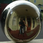
For our environment map I will use the chrome sphere image below. This image was provided in Bridget Gaynor’s Digital Lighting and Rendering Class. (Click for full rez)
Go into the material palette and apply a default material called reflective (under general shaders) to your model. In the parameters for this shader, set Lambert Intensity to 0 (effectively making the model 100% reflective), untick Use Base Color, Use Point Color and Use Point Alpha. In the Color Map tab, make sure Use Color Map is unticked. In the Specular tab make sure Specular Intensity is set to 0. In the Reflection tab, ensure that the Reflection Intensity is set to 1. Under that tab, in the Ray Trace tab, make sure Use Ray Tracing checkbox is ticked. This will enable Self Reflections on your models by initiating multiple ray bounces based on the Ray Bias. Turn off Use Index of Refraction to stop the shader from scaling down the amount of reflected light based on an Index of Refraction value. With this value turned off, you will recieve 100% reflected light. As mentioned earlier, Ray Bias controls multiple ray bounces. The lower this value, the more ray bounces you will receive. The default value of 0.005 is usually good enough for complex models with self-reflection properties. Cone Angle will control the blurriness of the reflections, while Area Samples will smooth the result by sampling each pixel multiple times. In the Environment Map tab, point to your environment image. Feel free to use the image above.
Note: For sharper results in your render, be sure to use Ray Tracing in mantra as the Rendering Engine of choice.
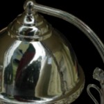
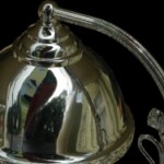
Below: Micropolygon Render on the left, Raytrace render in the middle, No self reflections on the right (Use Ray Tracing option turned off in the reflection shader).
Custom Reflection Shader
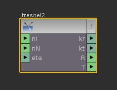
Now for the fun part. Building a reflection shader from ground up in VOPs. Go into the SHOP context and lay down a material node. Double click to go inside, and bring in a VOP VEX Surface SHOP using the TAB menu. The first thing we will have to do in here is to figure out the angle of reflection based on the Incident ray and the surface normal. We know that the angle between the ray of incidence (light ray) and the surface normal is equal to the angle between the surface normal and the reflected light. To calculate that angle between the surface normal and the reflected light based on the ray of incidence, we can use a Fresnel VEX node.
Hit TAB and bring in a Fresnel VEX node.
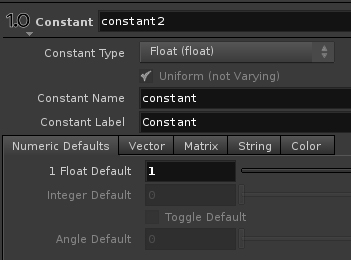
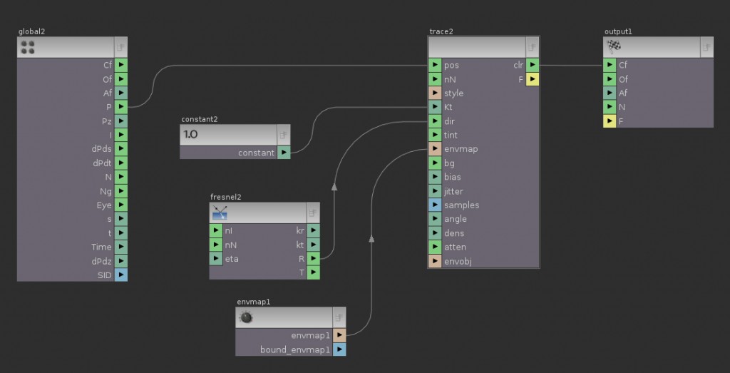
This node needs three pieces of information to function: nl (Normalized Incidence ray), nN (Normalized Surface normal) and eta (Index of Refraction). If nl and nN are not connected, this node will use the default Normal and Incidence ray values. In most cases this will be fine, unless you have manipulated these values prior to bringing in this node. In that case you will have to make sure that these values are normalized before connecting them to this node. You would use a Normalize node for that situation. In this case, we will just leave these inputs disconnected. Next, we will bring in a Trace VEX node. This node is responsible for sending a ray in the direction of the reflected ray and returning with a reflected color. From the Global Variables begin by connecting point position P to pos on the Trace VEX node. This will give the Trace node the origin of the reflected ray using a vex gather function. Next lay down a constant node and connect it to the Kt parameter of Trace. Make sure the Constant Type is float, and the 1 Float Default is 1. This will make sure that the reflection intensity will always be the maximum, equivalent to a 100% reflective surface.
Next, connect the Reflection Vector R output of the Fresnel node to the dir (Trace Vector) input of Trace. Finally, middle-click on the envmap input of the Trace to connect a new parameter. This will give the artist ability to add an environment map at the shader level. Similarly, you may want to connect parameter nodes to the tint, bg, bias, jitter, samples, angle, dens, atten and envobj inputs of the Trace node. Here is the network of our very basic reflectivity shader. Click for full resolution:
The results of this shader gives you reflections with self-reflections for complex objects. Naturally, for the complex objects we will need to extract JUST the self reflections for composting purposes.
Self-Reflections Matte
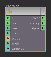
There isn’t really a direct way for getting this specific pass using default shaders. At-least not that I know of. But never fear. It’s actually not that hard to get self-reflection information using the Ray Trace VEX node. This node shoots a ray starting at each surface point into a direction specified by the fresnel node. It can thus determine the resultant color, opacity and alpha of the ray. Since self-reflection results in multiple ray bounces as opposed to a direct reflection, it means that any direct reflection will receive an opacity of zero where it intersects with a self-reflection. This is where we will use the opacity output of this node in an interesting way :
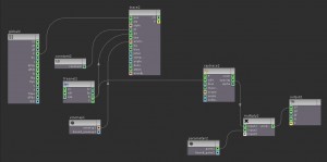
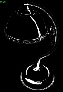
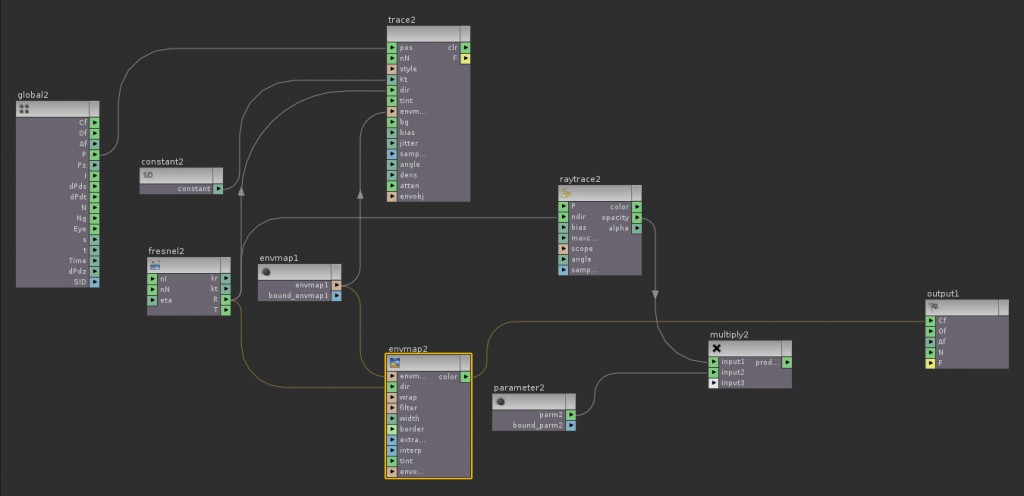
We will integrate this new network with our currently existing one. Hit TAB and bring in a Ray Trace VEX node. The first input it will need is P, the Ray Origin. Leave this disconnected and the node will use the surface value for P, which is fine here. The next input needed is the ndir, normalized ray direction. This needs to be connected to the R output of the fresnel node. Now connect the opacity output of the raytrace to the Cf (surface color) of the Output Variables node. Render the result. Below is the modified network. You should get a black and white render with this result:
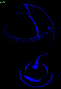
The white areas are the self-reflection. They are the points that have opacity set to 1 because of occlusion by secondary bounces. To change the matte color, drop a multiply node and connect the opacity output of raytrace to input1 of the multiply. Drop in a new Parameter node and change the Parameter Type to Color. Connect this Parameter node to input2 of the multiply node. Connect the product of the multiply to the Cf variable. Go up one level to change the Color parameter to a primary color Red Green or Blue. You can use this matte pass to manipulate self reflections in post if you so desire:
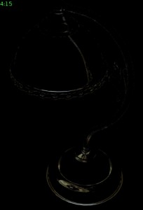
Note: Theoretically, you can isolate the self-reflection result by sending the clr output of the Trace node to input2 of the multiply, effectively replacing the color parameter. However, this option produced some errors using my model. For me, I am not getting all of my information in the self-reflections. I can’t quite figure out why, since this technique should clearly work also. Here are the results:
Left – Raytrace opacity result, Middle – Opacity result times blue color, Bottom – Opacity result times Trace output
In my results, when multiplying the Trace color result by the opacity, I only get some of the self-reflect information and not all. In the blue matte pass however, you will be sure that you’re isolating all of your reflection information.
Custom Shader Without Self Reflections
Earlier in this lesson we used a default Houdini shader to render our model WITHOUT self-reflections. We did this by turning off an option called Use Ray Tracing. For some reason you may want a render pass without self-reflections and one with. In our custom shader you can add this functionality with an Environment Map VEX node. This is effectively the same thing as turning off the raytracing functionality of our shader that inherently comes with the Trace VEX node. The Environment Map node needs two inputs to work in this way: envmap (the color map) and dir. (Direction of map application, in this case, the reflection vector) We already have an envmap parameter node connected to our Trace node, so we could copy the output of this parameter to our Environment Map node also.
Note!: Be sure to always change the Transform Space of the Environment Map (and any other color-mapping function) to space:world.
Finally, connect the R output of the fresnel node to dir input of the Environment Map. Connect it’s color output to the Cf output variable. Here is the adjusted network:
